The CW-219/220 range of vibration monitors offers a new and particularly application and user-friendly concept for monitoring the status of vibration levels and bearings in rotating machinery to provide vital early warning of impending damage.
High-performance hardware guarantees extremely flexible measurement value acquisition, analyse, output and communication. This makes it possible to offer the user a variety of task and price oriented models encompassing different monitoring functions. Concentrating on the "essentials" in conjunction with a learning mode reduces complexity for the user – and considerably cuts down the time required for installation and start-up.Distinguishing features of the individual versions of this product range vary with regard to their digital interfaces to support control tasks as well as their range of functions.
The basic version CW-219A offers efficient algorithms to monitor RMS level and transient shock pulses as often occur when roller bearings develop defects over time. The CW-219B and CW-219C offer extended functionality, such as crest factor, more flexible RMS settings as well as a long-term trend recorder. Adjustable alarm thresholds that respond to process-input variables are as equally possible as it is to monitor narrow band levels. The CW-220C offers the complete range of functions to meet the demands of even more complex monitoring tasks, including monitoring variable speeds.
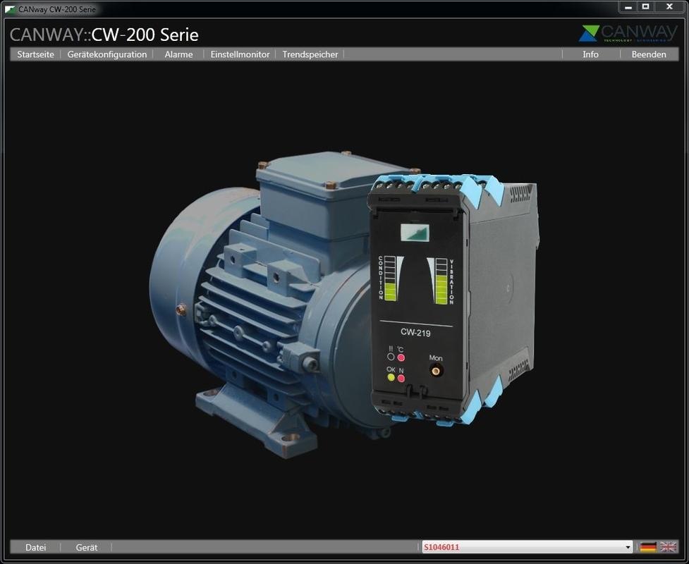
The concept behind the CW-200 range, above all the spatial distance between the measuring sensors and where signals are evaluated, offers the user extremely high levels of flexibility when selecting the appropriate sensor to meet application requirements (sensitivity, frequency response, design type, costs) and installing the vibration monitor. Because different sensor design types are available to meet requirements of different applications, this concept allows the sensor to be installed in the most suitable position – even in the harshest of conditions (e.g. high ambient operating temperatures).
The machine condition monitors of the CW-200 range are 100% digital, DSP-based systems. Each device offers connection options for ICP® sensors (accelerator sensors, pressure transducers, microphones), for temperature sensors as well as inputs to measure speed or even current and voltage signals (measure power consumption). CW-220C systems are also equipped with inputs to directly connect inductive/digital speed or position reference sensors.
Up to three galvanically isolated current sinks (4-20 mA) guarantee signal transmissions to the higher-level monitoring system or controller (PLC). The user is able to assign the output and relevant measurement variables according to requirements.
Each of the CW-219/220 devices is equipped with two galvanically isolated relay outputs for signalling or alerting to practically unlimited user-definable events (pre-alarm or main alarm).
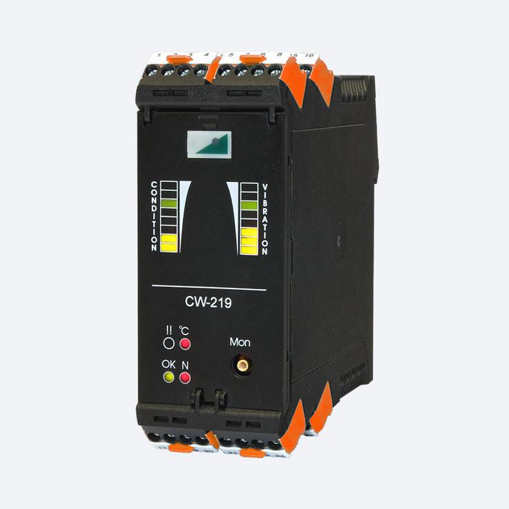
The output socket on the front of the device facilitates direct pick-up of the measurement signal from the ICP® sensor for analysis by means of an oscilloscope or FFT analyzer.
Configuration, parameter settings as well as online output of measurement and analyzer data are implemented via CAN bus; other interfaces (LAN/WLAN, EtherCAT) are optional. An adapter cable for direct USB connection to a PC is included in the scope of supply.
The CW-219/220 is equipped with an extensive range of internal safeguarding mechanisms. For instance, it is only possible for a main alarm to be triggered when all components are functioning properly.
A watchdog signal continuously checks the processor is functioning correctly. A self-test mode also continuously checks the entire ICP® measuring chain through to the sensor: Short-circuits and cable breaks along the sensor line are detected immediately; a designed-in safeguard that prevents false alarms.
It is optionally possible to signalize a malfunction by activating one of the two output relays.
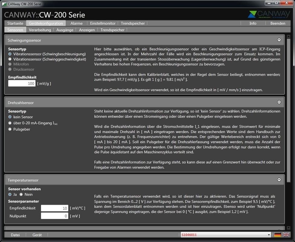
All inputs and outputs, measurable variables, evaluation processes and limit values are configured using a PC. The parameters are transferred via CAN bus (interface option 01) or Ethernet (interface option 02). The clearly structured and intuitive user interface of the software belonging to the CW-200 series guides the user through all the settings. Online recommendations and comprehensive explanations detailing the significance of settings for machine monitoring support the user throughout the configuration process. This approach ensures CW-219/220 parameters are assigned error-free within the shortest time possible. A summary allows users to check their CW parameter settings and approve the configuration before they are transferred. It is also possible to save the summary to text files for documentation purposes, for example. Final approval is required before device settings including alarms become active and machine monitoring is started.
It is possible to extend the operating software of the CW-200 range of models with various software modules to add signal recording and analysis options: For fault analysis purposes a short-term mode scans and stores selected measurable variables in millisecond cycles. To facilitate trend analyses it is possible to store peak or mean values of calculated condition variables on a daily basis or even per shift in the long-term mode.
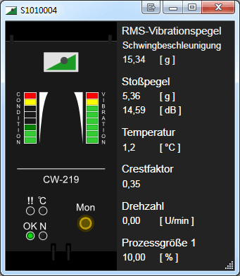
Two LED arrays on the front of the device ensure operating personnel are quickly able to assess the condition of the monitored machine. According to configuration settings these indicate the current level of vibration as well as a further pre-determined condition variable (for example, transient shock level). The LEDs indicate if vibration values exceed previously defined limits as equally if a temperature or speed limit value is exceeded. Moreover, the device also signalizes that the complete measuring chain is functioning without any faults.
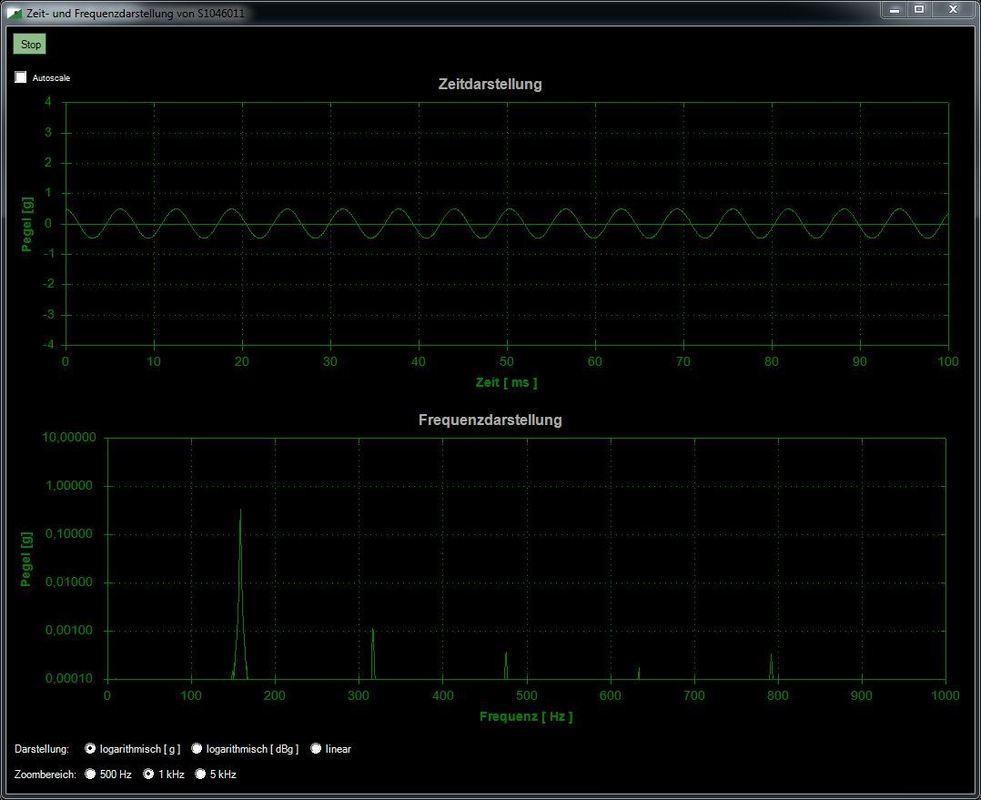
In addition, it is also possible to graphically display the indicator elements used to monitor and analyze the condition of the machine on a master computer or PC. To provide the user with an additional form of support when setting and checking configuration parameters, the CW-200 series also offers the option of carrying out orientation measurements displaying time and frequency.
CW-219 series models are able to measure (constant) speeds via a current input. This allows the user to define speed-dependent alarm thresholds, for example. Scaled accordingly, the measured speed information can in turn be output via a 4-20 mA interface and, consequently, utilized for control and monitoring purposes. The CW-220 model has been designed for monitoring tasks in systems operating at variable speeds, including the monitoring of speed-dependent narrow band levels (optionally with selectable relative or absolute bandwidth). It is equipped with a speed input with corresponding signal conditioning for direct connection with an inductive or digital rotary encoder.
It is possible to extend the functionality of the CW-200 range at any time vis-a-vis the number of channels and algorithms. Controlled via a single bus and a common configuration screen, it is possible to deploy practically any number of devices independent of one another. In addition to the option to extend the number of channels, CW-220 type models are also designed to facilitate cascading and synchronization. It is possible to control the devices jointly or individually via CAN bus (with CW-102 also via Ethernet) and extend their functionality at any time by implementing upgrades.
Hardware and software modules are available to extend the basic functions of the CW-200 range:
1. Interface option 01: CAN USB connection via cable adapter CW-101
2. Interface option 02: Ethernet by additional interface CW-102 for LAN
3. SW module 01: Several selectable frequency bands to monitor associated RMS level
4. SW module 02: Low speed option for speed ranges up to max. 600 rpm on request
All modules of the CW-200 series make use of modern signal processors for monitoring and analysis tasks: That makes it possible to implement additional application and customer-specific evaluation processes for atypical monitoring tasks. As a consequence, the CW-200 series offers a flexible and efficient platform to meet your requirements - including custom and OEM solutions.
| Units with constant speed | Units with variable speed | |||
|---|---|---|---|---|
| CW-219A | CW-219B | CW-219C | CW-220C | |
| MEASUREMENT VARIABLES/INPUTS | ||||
| Vibration, ICP® input | √ | √ | √ | √ |
| Process variable 1: Current input (4-20 mA) | √ | √ | √ | √ |
| Process variable 2: Current input (4-20 mA) | √ | √ | √ | √ |
| Process variable 1: Voltage input (0-2 V) | √ | √ | √ | √ |
| Speed, inductive or digital sensor | ||||
| Differential input (position mark) | on request | on request | ||
| CALCULATED VARIABLES | ||||
| RMS value of vibration acceleration | √ | √ | √ | √ |
| RMS value of vibration velocity | √ | √ | √ | √ |
| Shock level to monitor bearings | √ | √ | √ | √ |
| Crest factor | √ | √ | √ | |
| Narrow band level | 2 bands | 3 bands | 3 bands | |
| Speed controlled narrow band level | 3 bands | |||
| OUTPUTS | ||||
| Scalable current outputs (4-20 mA) | 2 | 3 | 3 | 3 |
| Relay outputs | 2 | 2 | 2 | 2 |
| CAN bus | √ | √ | √ | √ |
| LAN (with CW-102) | Optional | Optional | Optional | Optional |
| Vibration time signal (monitor connector) | √ | √ | √ | √ |
| OTHER FUNCTIONS | ||||
| Learning mode | √ | √ | √ | √ |
| Extended RMS frequency band settings | √ | |||
| Flexible RMS frequency band settings | √ | √ | ||
| Long-term trend memory (flexible setting options) | √ | √ | ||
| Process-variable dependent alarm thresholds | √ | √ | √ | |
| Multidimensional performance data sets for alarm thresholds | on request | on request | ||
| Sensor type: | Dual sensor to measure vibration and temperature or discrete vibration sensors Vibration: IEPE (ICP®), 4 mA bei 20—30 V, Sensitivity 10—1000 mV/g, Resolution 4 mg with sensitivity 100 mV/g |
| Signal ranges: | Dynamic: Autoranging up to 50 g |
| Digital weighting filter: | Transient shock: RMS level: Applies only to CW-219B: Applies only to CW-219C/CW-220C: |
| Process variable 1: | Current (0 – 20 mA), scalable signal range, e.g. for speed, temperature, load, pressure, etc. |
| Process variable 2: | Current (0 – 20 mA), scalable signal range, e.g. for force, load, speed, differential pressure, etc. |
| Process variable 3: | Voltage (0 – 2 V), scalable signal range, e.g. for dual vibration/temperature sensor |
| Speed input: | Active or passive rotary encoder (e.g. inductive sensor) |
| Number of pulses: | 1 - 720 pulses per rotation, adjustable |
| Maximum frequency: | 36 kHz |
| Reference pulse: | 1x per rotation to determine position |
| Current interface: | 4 – 20mA signal range, galvanically isolated, with 2 mA alarm (adjustable), Displays |
| Switching relays: | 1x NO, 1x NC with safety control circuit Configurable alarms Max. switching voltage: 48 V, max. switching current: 1 A |
| Monitoring: | Non-weighted analogue sensor signal (picked up behind pre-amplifier) |
| Configuration and online mode: | CAN (optional: CANopen, CAL, etc.) USB in conjunction with CW-101 LAN, WLAN in conjunction with CW-103 |
| Supply voltage: | 24 VDC nominal (20—30 VDC) |
| Current consumption: | Approx. 80 mA at 24 V |
| Galvanic isolation: | Current interfaces, CAN |
| Temperature range: | -10 °C to +70 °C |
| Degree of protection: | IP20 |
| Housing: | Top-hat rail housing with screw terminals (WxHxD: 45 x 120 x 120 mm³) |
| Certification: | CE |
Back to the overview | CW-200 Series